UML State Model
Content may include inaccuracies, outdated information, or technical errors. Users are advised to cross-check critical information before implementation.
The notation follows UML state diagrams: the states of an object and the transitions between them.
Create the model and the machine
Create a model of the type PlantUML State Model and open its diagram.
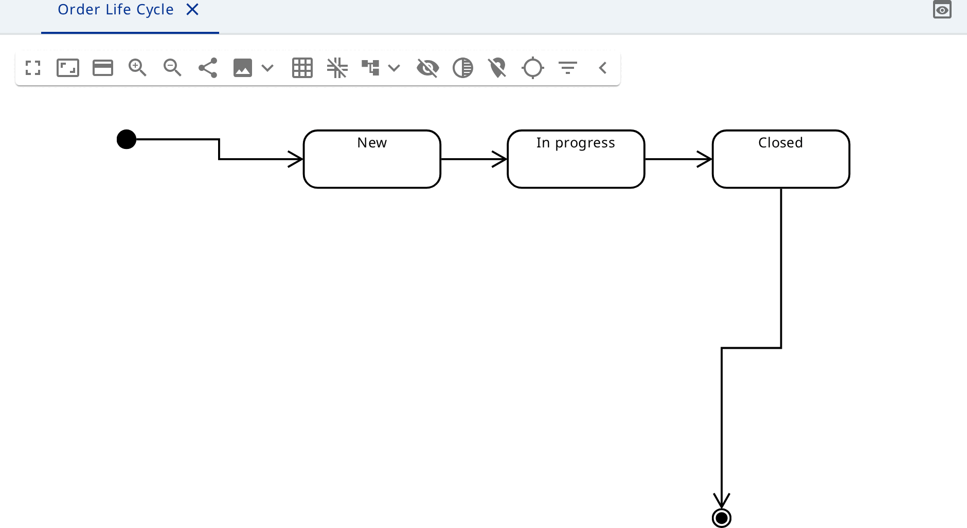
Click the background and create an Initial State, the states New,
In progress and Closed, and a Final State. Join them with Transition
relationships:
- initial state →
New; New→In progress, namedaccept;In progress→Closed, namedcomplete;Closed→ final state.
A transition joins two states with the same owner, so all four transitions stay at the top level of the model.
A composite state
The state In progress covers several stages. Click it and create a State
Picking inside. A Region appears within In progress - the dashed frame
around Picking.
Add the states Packing and Shipping to the same region, and an Initial
State before Picking. Join them in order. Transitions drawn inside a region
belong to the region, so the inner sequence stays with the composite state.
A second region
If shipping and invoicing happen at the same time, click In progress and
choose Region. A second frame appears next to the first: fill it with the
states Invoicing and Invoiced, each with its own initial state.
Two regions of one state work in parallel: the order passes through both at once.