UML Activity Model
Content may include inaccuracies, outdated information, or technical errors. Users are advised to cross-check critical information before implementation.
The notation follows UML activity diagrams: the steps of a process, branching and merging of the flow, parallel branches, the start and the end.
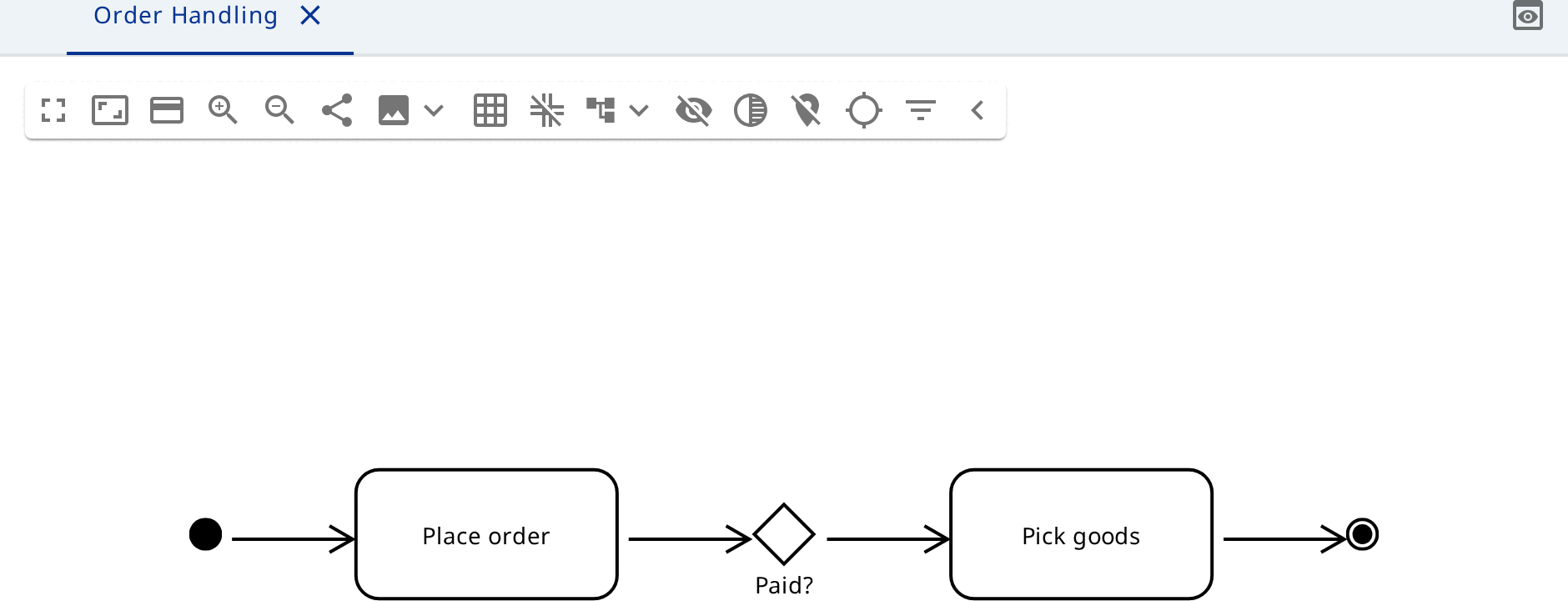
Create the model and the lanes
Create a model of the type PlantUML Activity Model and open its diagram.
- Click the diagram background and choose Activity Partition. A lane
appears, together with the Activity Partition Set that holds it. Name the
lane
Customer. - Click the
Customerlane and choose Activity Partition (after). Name the second laneWarehouse.
The customer lane
In the Customer lane create an Initial Node, an Opaque Action
Place order, a Decision Node Paid? and an Activity Final Node.
Join them with Control Flow relationships: initial node → Place order →
Paid?. Draw the first flow out of the decision node, name it no and send it
back to Place order.
The warehouse lane
In the Warehouse lane create the actions Pick goods and Ship order.
Draw the second flow out of Paid? to Pick goods and name it yes. Then join
Pick goods to Ship order, and Ship order to the final node in the customer
lane.
Control flows cross lane boundaries, so the diagram reads as one process handing work from lane to lane.
Parallel branches
If picking and invoicing happen at the same time, add a Fork Node after
Paid? and a Join Node before Ship order. Send one branch through
Pick goods and the other through a new action Issue invoice. Both branches
meet at the join node.
Activity and Activity Partition own their content - nodes, edges and groups - so processes nest to any depth.